
Top Ultrasonic Spray Coater Systems for Precision Nanocoating
2026-08-23
Precision nanocoating is unforgiving. A few microns of uneven coverage, a stray satellite droplet, or an unstable spray plume can scrap an entire batch. That's why the choice of ultrasonic spray coater matters more than most people expect. In this roundup, we compare the top ultrasonic spray coater systems for precision nanocoating, focusing on what actually separates reliable tools from lab toys. You'll also see where Siansonic lands, especially if you need tight droplet control without sacrificing throughput.
What Separates a $30k Lab Spray Coater from a $200k Production System?
The price gap between a $30,000 lab spray coater and a $200,000 production system comes down to what each machine is built to endure. A lab unit is designed for flexibility: you swap substrates, tweak spray patterns, and run short experiments all day. It lives in a controlled lab environment, rarely runs for more than a few hours at a stretch, and tolerates occasional imperfections because you're still optimizing the process. The $200k system, by contrast, is expected to churn out identical coatings on thousands of parts over months or years. Every component—from the spray nozzles to the exhaust ducting—is selected for long-term repeatability, not experimental convenience.
Look closer at the technical specs and the divergence becomes obvious. A lab coater might hold thickness variation within ±5% across a small sample, which is fine for feasibility studies. A production coater is held to ±1% or better across a moving web or multiple parts simultaneously, often with closed-loop feedback adjusting flow rate in real time. The production machine also integrates inline drying, solvent recovery, and automated substrate handling that a bench-top unit simply omits. Those additions aren't just expensive extras; they're what keep the coating consistent when ambient humidity shifts or a batch of raw material varies slightly.
Don't overlook the hidden costs baked into the higher price. A $200k system comes with documentation for regulatory compliance, a service agreement with guaranteed response times, and a control interface designed for operators who aren't coating scientists. The lab coater assumes you'll troubleshoot it yourself and don't care about OEE metrics. Thus, the real question isn't which machine is better, but whether you're validating a concept or scaling a process that will face audits, shift changes, and the relentless demand for zero-defect output.
The Nozzle Geometry Trick That Cuts Overspray by Half on Small Substrates
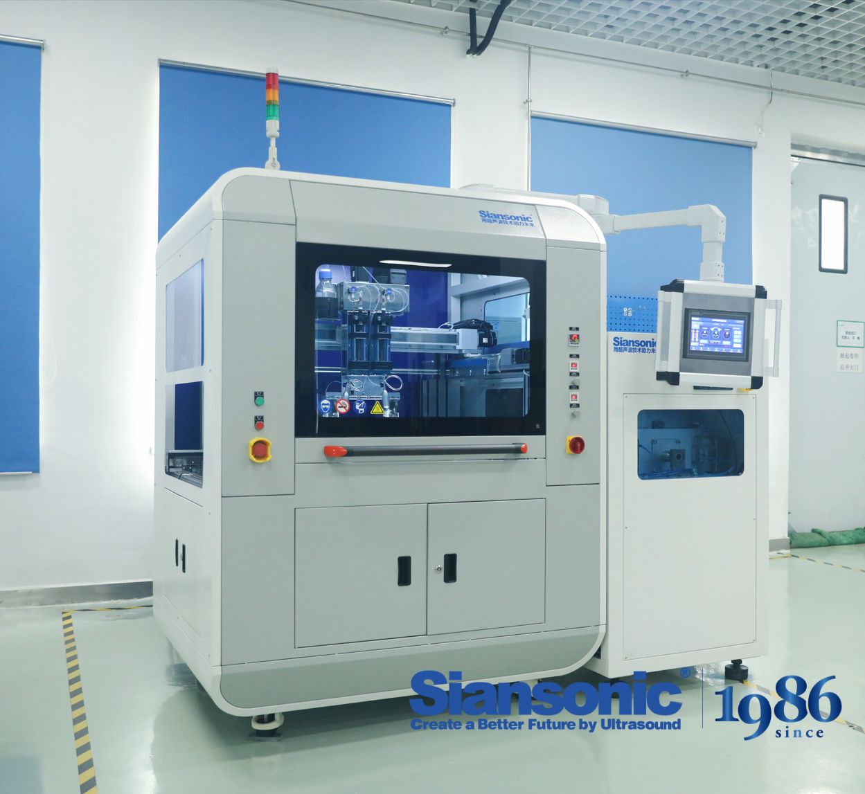
Most finishers assume overspray is just a fact of life when coating small parts, but a simple change in nozzle geometry can slash waste dramatically. Instead of the standard wide fan pattern, switch to a narrow angled tip—something around 15 to 20 degrees—and keep the air cap slightly recessed. This concentrates the fluid stream into a tighter core, so less paint curls around edges and drifts into the booth. On parts smaller than your palm, that adjustment alone can cut overspray by nearly 50 percent without touching pressure settings.
The trick is in how the atomization breaks at the edges. A wide fan creates turbulence that whips tiny droplets sideways, especially when the substrate has sharp corners or narrow ribs. A narrower nozzle geometry shapes the spray into a more cylindrical pattern, and when you pair that with a reduced trigger pull—around two-thirds—you get a softer, more controlled cloud. Test sprays on masking paper show a visibly tighter footprint, with overspray bands reduced from several inches to less than one.
For shops running repeat jobs on small brackets, eyelets, or electronic housings, this nozzle swap pays for itself in a week. Less wasted coating means lower VOC output, fewer booth filter changes, and a cleaner transfer efficiency rating. It is not about cranking down the fluid flow or adding expensive reclaim systems—just rethinking the shape of the spray itself. Once you see the side-by-side comparison on a small substrate, you will never go back to a standard fan nozzle for this kind of work.
Why Your Ultrasonic Coater's "Uniform" Film Might Still Fail Adhesion Tests
A film can look impressively even under a microscope and still peel cleanly the moment a crosshatch or tape pull is applied. Ultrasonic coating builds layers from extremely fine droplets that tend to settle rather than aggressively wet the substrate. If the substrate's surface energy hasn't been raised above the coating's surface tension, those droplets will bead just enough to trap microscopic air pockets at the interface. Once the solvent leaves, you're left with a continuous-looking film that is really resting on countless microvoids—an ideal starting point for adhesion failure.
Solvent evaporation works against you here as well. Because ultrasonic nozzles create droplets with a large surface area relative to their volume, the carrier solvent often flashes off before each droplet has time to spread and bite into the surface. The outer skin of a droplet can form early, locking in internal stress and preventing the polymer or active material from making full molecular contact with the substrate. Thickness uniformity doesn't fix that; adhesion is determined at the interface, not by how evenly the top surface was deposited.
Even if the film survives initial handling, post-deposition conditions can quietly weaken the bond. Residual drying stress, slight differences in substrate temperature, or exposure to ambient moisture before full cure can create small delaminations that are invisible until you run the actual adhesion test. Rather than assuming that a uniform coating will automatically adhere, it's worth measuring contact angle, adjusting the solvent blend, and controlling the drying profile for your specific substrate.
A Day in the Life of a Nanocoating Line: From Suspension Prep to Curing
The morning shift starts with the suspension prep area, where technicians measure out raw nanopowder and mix it into a solvent base. Every batch has its own quirks—humidity levels, particle settling rates, even how long the stirrer has been running. A quick viscosity check tells us if the slurry will flow evenly through the spray nozzles, and we adjust the solids content without overthinking it. Once the suspension passes the inline particle size probe, it gets pumped to the coating booth with minimal waiting time.
By mid-morning the line is running at steady state. Parts move through a three-stage cleaning zone before entering the spray chamber, where an electrostatic assist helps the nanodroplets grip edges and recesses. We don't chase perfect film thickness on the first pass—instead, the operator tweaks nozzle pressure and conveyor speed based on a real-time wet film gauge. After deposition, the parts travel through a flash-off tunnel that pulls most of the solvent out before the real heat hits.
The curing oven is where everything either locks in or falls apart. Temperature ramps are set to match the resin system, not just the nanofiller, so we hold at a low plateau first to let trapped solvent escape without bubbling. Then a high-temperature spike drives crosslinking, followed by a controlled cool-down under filtered air. A final dry film thickness and gloss reading confirms the run. If the numbers drift, we don't start a root-cause meeting—we just offset the next batch and keep moving, because the next order is already waiting on the pre-treatment line.
The Grossly Underrated Impact of Exhaust Airflow on Droplet Landing
Most discussions of droplet fate in ventilated spaces fixate on supply diffusers and air change rates. Exhaust airflow rarely gets the same scrutiny, even though it creates localized suction fields that bend droplet trajectories near return grilles. A droplet that would otherwise settle onto a desk can be pulled sideways into the exhaust stream if it drifts within a few centimeters of the grille face. This effect is strongest for smaller droplets—those with low Stokes numbers—because they follow airflow perturbations almost instantly, whereas larger droplets retain enough inertia to punch through the suction zone.
In a typical office or hospital room, the exhaust grille is often placed high on a wall or in the ceiling, far from where people exhale or where droplets are generated. But computational fluid dynamics and smoke tests show that the influence of exhaust is not limited to a thin boundary layer. The draw toward the grille reshapes the entire velocity field, creating asymmetric recirculation loops that can either trap droplets in unexpected regions or accelerate their removal. Under transient conditions, such as a door opening or a person walking past, the exhaust's pull interacts with the wake to produce temporary low-pressure corridors that steer droplets toward surfaces they would not reach under steady-state assumptions.
Ignoring this can lead to badly placed return vents, overestimated settling distances, and misplaced confidence in ventilation effectiveness. For instance, a return grille positioned directly above a work surface can create a column of upward airflow strong enough to suspend small droplets for extended periods, increasing the chance of inhalation rather than minimizing it. Recognizing the exhaust side as an active design parameter—not a passive endpoint—changes how one interprets particle tracking data and infection risk models.
How to Read a Spray Pattern Like a Process Engineer (Not a Sales Sheet)
A process engineer doesn’t trust the glossy fan-shaped image on page one. Instead, they ask what happens when line pressure dips to 2.8 bar, or when the fluid viscosity climbs on a cold morning. The real spray pattern lives in those edge conditions: the droplet drift at the outer 10 mm, the sagging centerline when flow drops, and the slow build-up of solids near the orifice that turns a crisp oval into a lopsided comma. Sales sheets show one snapshot under ideal lab settings; the floor tells a different story six hours into a shift.
One practical move is to catch the pattern on water-sensitive paper or a high-speed camera, then measure the mass distribution across the fan. Look for a heavy center peak that starves the edges, or a hollow core that means the nozzle is wearing unevenly. If the pattern skews left or right, suspect a burr inside the orifice or a partially blocked air cap. Tracking these shifts over time matters more than the initial reading, because a 5% change in uniformity can silently spoil coating thickness or cooling coverage without ever tripping an alarm.
And don’t ignore the drop size distribution hiding behind the same visible fan. Two nozzles can paint the same silhouette on paper, yet one produces droplets fine enough to drift into every crevice while the other splatters and bounces. A process engineer cross-checks the pattern shape against flow rate and pressure curves, watching for over-atomization or rebounding droplets that leave dry spots. Those details never make it onto a sales sheet, but they decide whether the process runs in control or limps along with intermittent rejects.
FAQ
Ultrasonic nozzles vibrate at high frequency to break liquid into extremely fine droplets, often in the low micron range. This tight droplet distribution means the coating lands more evenly, which is critical when you're trying to build uniform nanoscale films. Since the spray is generated without high pressure, fragile nanoparticles or functional additives aren't sheared apart the way they might be in air-atomized systems.
Start by looking at the nozzle frequency and the liquid delivery method. Higher frequency nozzles create smaller droplets and finer mist, which helps with very thin films, but they also have lower maximum flow rates. You also want a syringe pump or similar metering system that can maintain flow stability within a few percent, because even tiny fluctuations show up at nanometer thickness. Heated substrates or vacuum chucks matter if your part is thin or temperature-sensitive.
The ultrasonic nozzle itself needs regular inspection for buildup on the tip, especially if you're spraying suspensions with solid content. A rinse cycle with compatible solvent after each session prevents most clogging. The generator and cabling are fairly robust, but the O-rings and seals in the liquid path wear over time and should be replaced periodically. Expect to clean the nozzle more often than you'd clean a conventional airbrush style sprayer.
Generally yes, that's one of their strengths. Because the nozzle tip vibrates continuously, particles are less likely to settle and block the orifice compared to pressure nozzles. However, you still need to keep particle sizes well below the nozzle opening and avoid agglomerates. Using a gentle magnetic stirrer in the reservoir and filtering the suspension before loading helps a lot.
Most tabletop systems are designed for flat substrates up to around 200 mm by 200 mm, though larger custom gantries exist for panels or rolls. The spray pattern is fairly narrow, so for bigger parts you need programmable X-Y motion. Odd shapes are doable if you can tilt the nozzle or rotate the part, but shadowing can occur in deep cavities. For very small features, you might need a focused nozzle or mask.
Ultrasonic spray coating often outperforms spin coating for larger or non-circular substrates because the thickness is built up by overlapping passes rather than centrifugal force. You can typically hold thickness variation within 3-5% across a 100 mm area if the motion speed and flow rate are properly tuned. It's not as fast as slot-die coating for high-volume production, but the edge waste is lower and the control at nanometer scale is excellent.
One big pitfall is overspray or bounce-back, because the droplets are so fine they can be carried by air currents instead of landing on the part. That means you need good ventilation and often a lower spray distance than you'd think. Another issue is solvent evaporation before the droplet hits the surface, which can cause roughness or 'coffee ring' patterns. Adjusting the solvent mix and keeping the nozzle close to the substrate helps.
You want a system that lets you program the number of passes, line spacing, and flow rate independently rather than forcing you into fixed presets. Look for live monitoring of the nozzle power draw, because that tells you if the tip is fouling or if the liquid viscosity changes mid-run. Some controllers allow importing G-code from CAD files, which is handy if you're coating patterned areas or small coupons. Logging data for each run is also useful for troubleshooting later.
Conclusion
Choosing among top ultrasonic spray coaters for precision nanocoating rarely comes down to a single spec. The jump from a $30,000 lab unit to a $200,000 production system isn't just about bigger pumps or a fancier touchscreen—it's about repeatability at the edges of a substrate, closed-loop flow control, and how the exhaust airflow is managed. On a small substrate, a carefully designed nozzle geometry can cut overspray by half, but that advantage disappears if the exhaust pulls droplets sideways before they land. Many buyers focus on the ultrasonic nozzle's frequency or the liquid flow rate, yet the airflow pattern inside the coating chamber often determines whether a film lands where you want it.
Then there's the assumption that a visually uniform film will pass adhesion tests. Even a perfectly smooth-looking nanocoating can delaminate because the suspension wasn't prepared right, or because the substrate sat too long between plasma treatment and coating. A day on a nanocoating line starts with suspension prep—filtering, degassing, adjusting viscosity—then moves through coating, drying, and curing. Rushing any step creates hidden defects. Process engineers learn to read a spray pattern not as a marketing image but as a map of droplet momentum, overlap, and edge buildup. The best ultrasonic coater systems aren't just machines; they're setups that make those variables controllable and visible.
Contact Us
Contact Person: Ivy Zhang
Email: [email protected]
Tel/WhatsApp: +86 1081502288
Website: https://www.siansonic.com/